

What is the Future Trends of Charging Gun Cable?
2025-10-15
In the rapidly evolving electric vehicle (EV) infrastructure, the Charging Gun Cable serves as the critical link between charging stations and EVs.
What Is a Charging Gun Cable & What Are Its Core Specifications?
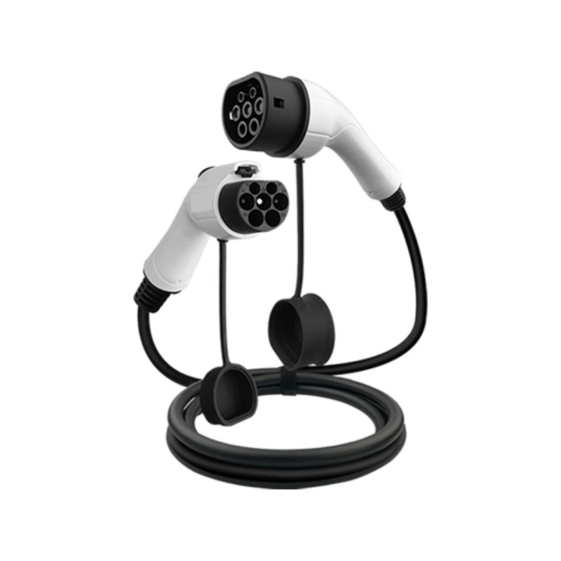
A Charging Gun Cable (sometimes called an EV charging connector cable or gun-to-vehicle cable) is a specialized high-voltage, high-current power cable integrated with a connector (the “gun”) on one or both ends. It is designed to deliver controlled DC or AC power from a charging station to an electric vehicle. The cable must meet stringent safety, durability, and performance standards to ensure reliable and safe energy transfer.
Key Product Parameters
Below is a representative specification table for an advanced Charging Gun Cable model, suitable for fast-charging and demanding usage environments:
| Parameter | Typical Value / Range | Notes / Implications |
|---|---|---|
| Rated Current | 125 A / 200 A / 300 A | Supports different charging power tiers |
| Rated Voltage | 800 V DC (often up to 1,000 V) | Compatible with high-voltage EV battery systems |
| Charging Mode | DC fast charge (CCS, GB/T, CHAdeMO) | Compatible with different standards |
| Cable Cross-Section | 35 mm² to 120 mm² (Cu conductors) | Balances flexibility vs. current capacity |
| Insulation / Sheath | EPDM + TPE / Nomex / XLPE | Must resist heat, ozone, UV, oil, aging |
| Inner Shielding / Drain wire | Copper foil or braid + drain cable | For EMI suppression and grounding |
| Operating Temperature | –40 °C to +85 °C (sometimes up to +105 °C) | Suitable for harsh climates |
| Bending Radius | 10 × outer diameter (min) | Controls flexibility and mechanical stress |
| Service Life | ≥ 10,000 cycles / 10+ years | Long lifespan under repeated use |
| Connector Locking Torque | As per standard (e.g. CCS locking pin) | Ensures secure mating |
| Safety / Compliance | IEC 62196, IEC 61984, UL, CE, RoHS etc. | Meets international regulatory demands |
This parameter set represents the high-end profile of what advanced Charging Gun Cables aim to deliver. Variations may exist depending on the market, standard (CCS, GB/T, CHAdeMO), and manufacturer design.
Why Does the Charging Gun Cable Matter?
Understanding the strategic significance of the Charging Gun Cable helps in recognizing why optimizing it is essential in EV charging networks.
Why Safety and Reliability Depend on It
-
High current & voltage risks: Any fault, overheating, or insulation breakdown can lead to dangerous arcing or fire. A robust cable with excellent insulation and internal monitoring is crucial.
-
Connector durability: Frequent mating/unmating cycles demand mechanical resilience. Poor design causes contact degradation or pin misalignment.
-
EMI / EMC compliance: High-power cables may emit interference. Proper shielding is mandatory to prevent interference with onboard electronics.
-
Temperature stability: Cables must withstand extremes — from subzero winters to scorching summers — without shifting impedance or insulation breakdown.
Why User Experience and Market Competitiveness Rely on It
-
Fast charging demand: Users expect high power, low waiting time. Cable gauge, thermal performance, and connector design impact how much current can safely flow.
-
Ease of handling: A heavy, rigid cable frustrates users. Lightweight, flexible design improves acceptance and usability.
-
Durability and warranty costs: A long-service cable lowers maintenance and replacement costs in large charging deployments.
-
Standard compatibility: Supporting multiple protocols (CCS, GB/T, etc.) widens market reach and cross-region interoperability.
Why the Industry Trend Focuses on Innovation
-
Higher voltages and currents: Moving toward 1,500 V systems to reduce losses and cable size.
-
Smart monitoring and sensors: Embedding temperature, current, humidity, and fault-detection sensors to enhance safety and predictive maintenance.
-
Lightweight materials: New conductor alloys, nano-material insulations, and composite sheaths reducing weight while preserving performance.
-
Modular / reconfigurable designs: Plug-and-play modules, retractable cables, or hybrid AC/DC switching capabilities.
By understanding these “whys,” decision makers can better prioritize quality, features, and innovation in Charging Gun Cable selection and design.
How Is a Charging Gun Cable Designed, Manufactured, and Applied?
This section walks through the life cycle of a Charging Gun Cable — from design decisions to real-world deployment. It also addresses common challenges and solutions.
How to Design the Cable (Concept to Prototype)
-
Requirement analysis
Specify current, voltage, standards (e.g. CCS, GB/T), ambient conditions, bending cycles, expected life. -
Conductor selection
Choose copper or copper alloy conductors, evaluate cross-sectional area to meet current density (<1.5 A/mm² for safety), plus skin effect at high frequency. -
Insulation and dielectric design
Multi-layer insulation (e.g. EPDM + XLPE) with controlled permittivity to limit electric field stress. Interface with shielding. -
Shielding and grounding design
Use copper foil, braided mesh, or drain wires to control EMI and provide ground paths. Ensure continuity through connector transition. -
Connector integration
Design the gun housing, internal contact pin geometry, locking mechanism torque, sealing (IP rating), and mechanical robustness (shock, vibration). -
Thermal modeling
Simulate heating under load, account for ambient, internal heating, thermal runaway safety margin. -
Mechanical design
Design for bend radius, flex fatigue, strain relief, and anchoring to the connector. -
Prototyping and testing
Build prototypes and test for dielectric strength, partial discharge, impulse voltage, thermal cycling, mechanical fatigue, waterproofing, etc.
How to Manufacture and Quality Control
-
Conductor extrusion and stranding: High-precision manufacturing ensures consistent cross-section and low resistance.
-
Insulation and jacketing: Controlled curing, crosslinking, and layering.
-
Shielding application: Braid or foil wrapping, drain wire termination to connector.
-
Connector assembly: Automated insertion of contact pins, proper crimping or brazing, and housing assembly.
-
Aging and electrical test: High-pot, partial discharge, insulation resistance, contact resistance.
-
Mechanical endurance tests: Repeated bending, plug/unplug cycles, vibration, drop tests.
-
Environmental testing: Salt spray, UV exposure, ozone, humidity, high/low temperature cycles.
-
Batch traceability and documentation: Markings, serial numbers, test reports, certificates.
How to Deploy and Maintain Charging Gun Cables
-
Correct sizing and installation
Ensure proper bend radii, protective conduit (if outdoor), strain relief, routing to avoid abrasion. -
Periodic inspection regime
Visual inspection, infrared thermography, insulation resistance test, connector cleanliness. -
Fault diagnosis and replacement procedure
Identify hotspots or insulation degradation and replace or repair modules. Use modular connector parts if possible. -
Upgrading or retrofitting
In high-power systems, upgrade cables or connectors as system voltage/current needs grow.
Common Challenges & Solutions
| Challenge | Solution / Mitigation |
|---|---|
| Excessive heating in extreme environments | Use higher temperature-rated insulation materials or active cooling |
| Connector wear and corrosion | Use gold/nickel plating, moisture-resistant seals, frequent cleaning |
| Electromagnetic interference | Proper shielding, twisted pairs for control lines, isolating sensitive circuits |
| Cable handling stiffness | Use fine stranding, flexible jackets, optimized cross-section |
| Compliance with multiple standards | Design modular or hybrid connectors supporting CCS, GB/T, CHAdeMO in one product |
By mastering how to design, produce, and maintain these cables, a manufacturer or infrastructure operator ensures performance, longevity, and user satisfaction.
Frequently Asked Questions (FAQ)
Q1: How long can a Charging Gun Cable last under heavy usage?
A1: Under proper design, material selection, and usage conditions, a Charging Gun Cable can achieve a service life of 10,000 or more mating cycles (typically equivalent to 8–15 years or more). Environmental stresses (heat, UV, humidity) and mechanical abuse may shorten lifespan, so regular inspection and preventive maintenance are critical.
Q2: Can one Charging Gun Cable support multiple charging standards (e.g. CCS and GB/T)?
A2: Yes, some advanced designs use modular or hybrid connectors permitting support for multiple standards. Internally, the cable must route the appropriate contacts and insulation layout for each standard. However, complexity, cost, and signal integrity must be addressed carefully in such multi-standard designs.
Future Trends and Industry Outlook
As the global EV ecosystem scales, Charging Gun Cable technology is poised for several key evolutions:
Ultra-high Voltage Systems (1,000–1,500 V)
To reduce current and I²R losses over long distances, new EV platforms and chargers will adopt higher voltages. Cables must adapt with advanced insulation, field grading, and connector designs.
Embedded Intelligence and Monitoring
Next-generation cables will integrate sensors for real-time temperature, humidity, bending stress, partial discharge, and wear. This allows predictive maintenance and improved safety.
Lightweight & Composite Materials
Emerging materials such as carbon nanotube-enhanced conductors, novel polymer composites, or graphene-based shielding layers promise lower mass without compromising performance.
Modular & Reconfigurable Cables
Future designs may adopt plug-in modules (e.g. replace just a worn connector end), telescoping or retractable cable lengths, or hybrid AC/DC reconfiguration in the same cable body.
Circular Economy & Sustainability
Cables will be designed for recyclability, recoverable metals, and lower embodied carbon materials to align with sustainability goals.
Standard Convergence & Global Interoperability
As standards gradually align, future cables could handle a broader range of protocols seamlessly, reducing the need for multiple cable types in international markets.
For deployments seeking reliable, high-performance charging infrastructure components, VanTon offers advanced Charging Gun Cable solutions tailored to modern EV applications. Contact us for specifications, custom designs, or partnership inquiries.